Build an OpenCat quadruped, from the kit to sim2real
OpenCat is the open-source framework Rongzhong Li started in a Wake Forest dorm room in 2016, and it drives two robots: Nybble, an 11 DOF cat, and Bittle, a 9 DOF dog. Ten micro servos, one board that fans out 16 PWM channels, a 1,000 mAh lithium pack, and a frame that snaps together without a drop of glue in under two hours. Upstream sells the construction kit at $319 and the set of ten servos at $119.99, so those lines are priced in the text rather than dressed up as a search. The six phases below follow the manual's own order, and the last one leaves the toy behind: a Raspberry Pi on the serial port, ROS, LiDAR SLAM and a walking policy trained in Isaac Gym.
IntermediateTarget budget €600.00From €367.88 with the cheapest option at every step
Parts and decisions taken from PetoiCamp/OpenCat-Quadruped-Robot github.com/PetoiCamp/OpenCat-Quadruped-Robot · MIT
1 · The bench, and what the kit already contains
The tool list is three lines: a flat and a Phillips screwdriver sized for M2, a computer to run the Arduino IDE or the Petoi desktop app, and a 5 V 1 A USB charger for the battery. Upstream states the design is glue free and asks you to avoid it, so nothing on the bench melts or sets. Work on a hard floor rather than carpet, because the springs of the upper legs and the M2 screws are the parts that vanish. The construction kit ships the body, the neck, the head, four pre-assembled upper legs, four lower leg pieces, ten P1S servos split into five with a long cable and five with a short one, the board, the battery, a USB cable, a self-tapping screwdriver, the M2 x 8 screws and the L-shaped calibration ruler. Two generations coexist and this repository targets the older one: Bittle and Nybble run the NyBoard, an ATmega328P board, while the current Bittle X V2 and Nybble Q run the BiBoard V1 on an ESP32 and are served by the OpenCatEsp32 repository. Upstream quotes 40 to 90 minutes for the assembly.
1.Screwdrivers for M2Buy it
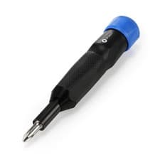
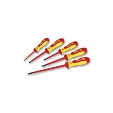
The whole robot is held by M2 screws, and the kit ships one self-tapping screwdriver. A flat blade and a Phillips in that size cover the rest, including the flathead screws that lock the legs onto a metal output gear. Nothing here needs torque; the plastic parts strip long before your wrist gives out.
Assembly
- Pick a driver whose tip actually fits M2, since an oversized blade rounds out the head on the first leg.
- Keep the self-tapping screws and the flathead screws in separate boxes, because they lock different joints and are not interchangeable.
- Work over a hard floor, so that a dropped spring stays findable.


2.5 V 1 A USB chargerBuy it
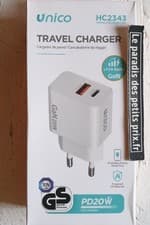
The pack charges through its own micro USB port and upstream asks for a 5 V 1 A supply, explicitly not a fast charger. It supplies nothing while charging, so the robot is off for the duration, and the documentation asks you to keep the pack in sight for that time.
Assembly
- Charge outside the robot and away from anything flammable.
- Watch the LED on the pack, red while charging and green when it is finished.
- Long-press the pack button for three seconds to switch it on, and check that the yellow LED on the board lights up with the blue one.



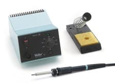
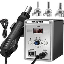
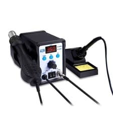
3.Soldering stationBuy it
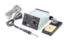
Nothing in the standard build needs an iron. It becomes necessary at exactly two moments: soldering the 2x5 socket that lets a Raspberry Pi sit on the NyBoard, and wiring a sensor that does not come with a Grove connector. Temperature control matters more than wattage on a board this dense.
Assembly
- Unplug the 6-pin USB adapter before mounting a Pi on the board, which upstream flags as a prerequisite.
- Solder the socket before the servos are wired, while the board can still be taken out flat.
- Accept that the Bittle back cover no longer closes once the socket is on, and plan the cable routing accordingly.
2 · The frame: ten servos and no glue
The cable length decides where each servo goes. The four long ones go into the lower legs, where the wire has to climb back up to the shoulder; the four short ones go into the shoulders and hips, and a fifth short one into the chin. That leaves one long servo as the spare. The chassis has a front and a back: the two large holes along the central track sit towards the tail, and a small A1 mark is moulded at the front. The neck clips into the chassis by its rear tip, then the front hook snaps down. Side shoulders and end plates assemble by tenons, three per side, and the two front tenons go in as one group so the plate stays square. The legs are mirrored left and right while front and back are identical, which means two pairs in opposite configurations rather than four identical legs. The lower leg wire passes through the notch moulded on the inner edge and gets folded before the servo is screwed down, because it is unreachable afterwards. The upper leg springs are the step that takes technique rather than force; they have been pre-assembled in kits since 2022.
4.Ten micro servos× 10Buy it
Nine joints and one spare. Upstream sells the set of ten alloy-geared units at $119.99 and fits P1S servos on Bittle, G41 on Nybble. What the firmware fixes is the interface rather than the mechanics: the P1S is driven over a 270 degree range, the G41 over 180, both with pulses from 500 to 2500 microseconds refreshed at 240 Hz instead of the usual 50. The joint command is then clipped to plus or minus 125 degrees. Any substitution has to accept 7.4 to 8.4 V directly, since the sockets sit on the raw pack.
Assembly
- Sort the servos by cable length before touching a screw, four long ones for the lower legs and four short ones for the shoulders and hips.
- Keep the fifth short one for the chin and the fifth long one in the box as the spare.
- Fold the lower leg wire through the notch on the inner edge before screwing the servo down.
- Do not power a 6 V hobby servo from these sockets, which sit directly on the two-cell pack.


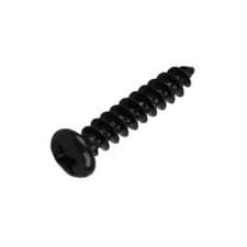
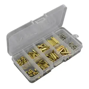
5.M2 screwsBuy it
The kit counts them exactly and the build eats around thirty. M2 x 8 self-tapping screws hold the servos in their windows, the neck onto its arm and the board onto its standoffs, two per part. The legs are locked at the very end with M2 x 4 flathead screws on a metal output gear or M2 x 6 self-tapping ones on a plastic gear.
Assembly
- Check which output gear your servos have before ordering, since the two screw types are not interchangeable.
- Stop tightening as soon as the part is held, because these threads are cut into plastic and only forgive being cut once.
- Order a few spares of the M2 x 8, which is the size used everywhere and the one you will drop.

3 · Wiring, board and power
The servo sockets follow a circular symmetry on the board, and the documentation is blunt about the trap: the joint index has no relationship with the PWM index silkscreened on the PCB, and you must not read those numbers during assembly. The mapping lives in the firmware, where a table sends joint 0 to the head, joints 8 to 11 to the shoulders and 12 to 15 to the knees, and leaves the indexes in between free for robots with more joints. Wire direction is the other rule: the black wire, or the darkest one, sits closest to the board. On the NyBoard the infrared receiver slides under the back plate so the VS1838B sees outside, and four M2 x 8 screws hold the board on its standoffs. Under the hood: an ATmega328P-AU at 16 MHz with 2 KB of RAM, 32 KB of flash and 1 KB of on-chip EEPROM; a PCA9685 at address 0x40 fanning out 16 twelve-bit PWM channels; an MPU6050 at 0x68 with its DMP, interrupt on D2; an 8 KB AT24C64 at 0x54 that stores the skills; the buzzer on D5 and the infrared receiver on D4. Four Grove sockets bring out the bus by signal type, I2C on G1, analogue A2 and A3 on G2, digital D8 and D9 on G3, digital D6 and D7 on G4. Power is the part that surprises people: the servos run straight off the two-cell pack at 7.4 to 8.4 V, so a 6 V hobby servo like an SG90 must never be plugged in. The logic sits behind an LM1117 at 5 V then an XC6206 at 3.3 V, and a separate TPS565201 supplies 5 V at 3 A for a Raspberry Pi. The battery is a 1,000 mAh, 7.4 Wh lithium pack with its own charge and protection circuit, charged at 5 V 1 A through a micro USB port, and it supplies nothing while charging.
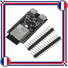
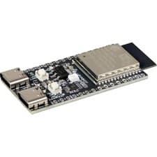
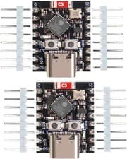
6.Controller boardBuy it
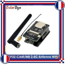
This repository targets the NyBoard, an ATmega328P running at 16 MHz with a PCA9685 fanning out the sixteen PWM channels, an onboard MPU6050 and an 8 KB I2C EEPROM for the skills. The current robots run the BiBoard V1 instead, an ESP32 with 4 MB of flash, twelve servo channels, Bluetooth and Wi-Fi, a voice recognition block and a Raspberry Pi port, fed from 7 to 9 V. Both are Petoi boards, so a substitution means porting the firmware rather than swapping a part.
Assembly
- Set the robot and the board revision in the sketch before the first upload, since the PWM pin table changed between NyBoard V0 and V1.
- Ignore the PWM indexes printed on the PCB during assembly, which the documentation states in the strongest terms.
- Plug each servo with the black wire closest to the board.
- Leave the I2C switch on the Arduino side until a Raspberry Pi actually takes over the bus.
7.Two-cell lithium packBuy it
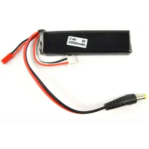
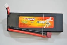
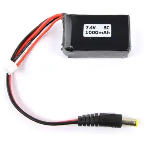
A 1,000 mAh, 7.4 Wh pack with its charge and protection circuit built in, sliding into a latched track under the body with no screws. Upstream measures several hours standing by, over an hour stepping on the spot and under thirty minutes running. The board reads the pack on A7 through a divider, so the real voltage is about twice the reading, and it starts complaining below 7.4 V.
Assembly
- Slide the pack in with its charging port facing the head, which is how the mass balances during motion.
- Plug the connector into the anti-reverse socket before switching anything on, a reversed connection being what kills a NyBoard.
- Treat the repeating melody as the low battery signal and stop, since the robot pauses its own movements at that point.
- Detach the pack from the body to charge it.

8.Wireless dongleBuy it
The NyBoard talks through a six-pin header that takes either a CH340 USB uploader or a dual-mode Bluetooth dongle, both at 115200 baud since 2021. The Bluetooth path is what the mobile app uses, and it is the one that makes calibration bearable, because you adjust an offset and watch the leg move without a cable pulling on the robot. On the BiBoard the radio is already on the chip.
Assembly
- Install the CH340 driver before plugging the uploader in, since a missing driver shows up as no serial port at all.
- Bend the six-pin socket forward in a smooth arc if no Raspberry Pi is going on the board, so the cover still closes.
- Keep the same baud rate on every port, 115200 on a V1 board and 57600 on a V0.


4 · Configure, calibrate, walk
The legs stay off the servos until the board has been configured. A servo powered for the first time lands at whatever angle it was left at, and a leg that jams against the body or another leg is a servo that burns out while you are looking for the cause. In the Arduino sketch you pick the robot with BITTLE or NYBBLE, pick the board version among the five NyBoard revisions, comment out MAIN_SKETCH and upload. The serial monitor answers at 115200 baud with no line ending: reset the joint offsets, then calibrate the IMU with the robot flat on the table, six long beeps, the offsets saved. Uncomment MAIN_SKETCH, upload again, and only now bring the robot into the calib posture, which sets all sixteen joints to zero. Five ways in: boot the robot lying on one side, the mobile app, the desktop Joint Calibrator, the serial command c, or the button at row three column three of the infrared remote. Attach head and legs perpendicular to the body, then fine-tune in software, because the servo output teeth are discrete and no mechanical alignment lands exactly on zero. The L-shaped ruler in the kit exists for that: the screw holes, the muscle line moulded on the thigh and the triangular hollow of the shank all line up with its openings. Screws go in last, M2 x 4 flathead on a metal output gear, M2 x 6 self-tapping on a plastic one. Servos made after March 2024 report their position back on the signal wire, which turns calibration into the c16 command, makes the other three legs follow one you drag by hand, and records up to 124 frames of a movement you demonstrate. That feature needs an ESP32 board and does not work on the NyBoard.
9.USB data cableBuy it
The configuration pass is two uploads with a serial dialogue in between, and it happens over a cable. On a BiBoard the cable goes to the board itself and not to the charging port of the battery, which looks identical from the outside and carries no data. A charge-only cable produces the same symptom: no port in the list, and an hour spent reading driver documentation.
Assembly
- Set the serial monitor to 115200 baud with no line ending before answering any prompt.
- Answer the joint offset reset, then the IMU calibration with the robot flat and still, and wait for the six long beeps to finish.
- Uncomment MAIN_SKETCH and upload a second time before attaching a single leg.


10.Printed calibration standPrint it
A stand holds the robot off the desk with its legs hanging free, which is what you want during calibration and during every programming session afterwards. Upstream publishes one in the NonCodeFiles repository and links two more on a model sharing site, one of which carries the calibration references directly on the frame. A few tens of grams of filament.
Assembly
- Print the stand before the first power-up, so the robot never stands on a table while the servos find their zero.
- Keep the L-shaped ruler from the kit even with a stand that carries its own references, since the two check different joints.
- Recalibrate after adding or removing mass, which moves the centre of gravity and changes what a correct posture looks like.


5 · The head is a sensor clip
Bittle's head is designed as a clip that holds a module, and the Grove sockets sort the modules by signal rather than by function. Loudness and light give an analogue reading and go on G2; touch, infrared reflection and PIR give a digital one and go on G4, which the demo code uses on D6 and D7; the camera, the PAJ7620U2 gesture sensor and the SSD1315 OLED talk I2C and go on G1. The constraint on the NyBoard is memory, not sockets: 32 KB of flash and 2 KB of RAM mean a module is enabled by a define and re-uploaded, and the header states plainly that enabling one disables the gyroscope code to make room. The combinations upstream declares workable are random behaviours plus ultrasonic, random behaviours alone, ultrasonic alone, voice, or camera. On the ESP32 boards you switch modes with a serial command instead. Some of this is already fitted depending on the model: Nybble carries the ultrasonic sensor, Bittle X carries the voice recognition module. The camera needs the MuVisionSensor3 library installed as a zip, its four dial switches set with the second one up for I2C, and the battery on, since tracking a ball means moving servos. Printed accessories live in the NonCodeFiles repository: a test stand that keeps the robot off the desk while you program it, a standoff for the Raspberry Pi, a reinforced neck lock, a camera mount, wide feet and a mount for the VL53L time-of-flight sensors.
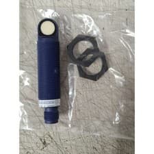
11.Ultrasonic sensorBuy it
Nybble carries one as standard and Bittle takes one in the head clip. It is the sensor that turns the robot from something you drive into something that reacts, and the firmware ships a mode for it. On the NyBoard that mode combines with the random behaviour module and with nothing else, because both are enabled at the cost of the gyroscope code.
Assembly
- Mount it in the head clip facing forward, where the neck servo can still pan it.
- Re-upload the firmware with the matching define, since a NyBoard module is a compile-time choice.
- Expect the gyroscope reactions to stop once the module is on, and decide which of the two the robot needs.


12.Camera moduleBuy it
An I2C vision module in the head clip gives ball tracking and body tracking without any computer on board, since the module does the detection and sends a result rather than an image. The firmware has a camera mode for it, and upstream publishes a printed mount. Anything heavier than this belongs on a Raspberry Pi in the next phase.
Assembly
- Install the vision library as a zip in the Arduino IDE before compiling the camera mode.
- Set the module's dial switches to I2C, which is the second one up on the reference module.
- Power the battery on for the tracking demo, since a robot that tracks is a robot that moves servos.
- Press the reset button on the module and then on the board after the upload, in that order.
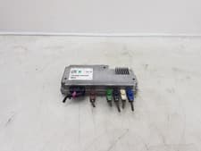
eBayIn stock
MODULE CAMÉRA CAMERA MODULE Porsche Panamera (971G) 2017 971907428F #311441
€420.00
View at seller ↗
eBayIn stock
MODULE CAMÉRA CAMERA MODULE Mini Clubman (F54) 2017 939924701 / 66519399247
€60.00
View at seller ↗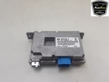
13.Grove sensors on the digital socketBuy it
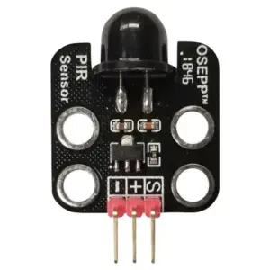
Touch, infrared reflection and passive infrared all return a one or a zero, and all go on the digital Grove socket, which the example code reads on D6 and D7. They are the cheapest way to give the robot a trigger: a hand passing overhead, a floor edge, someone entering the room. Loudness and light work the same way on the analogue socket.
Assembly
- Match the socket to the signal, digital on G4 and analogue on G2, rather than to whichever connector is free.
- Read the Grove logic level before wiring a bare sensor, the I2C socket being at 3.3 V while the others are at 5 V.
- Test one module at a time with the test sketch shipped for it, before putting it in the main firmware.



14.OLED screenBuy it
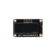
A small I2C display on the head is the cheapest debugging output on a robot with no screen and, half the time, no cable. It shares the I2C socket with the camera and the gesture sensor, so the three of them compete for one connector and for the flash the module code takes.
Assembly
- Check the controller reference against the test sketch, since the driver differs between OLED generations.
- Print the battery voltage on it, which is the reading the robot otherwise only reports through a melody.
- Add a Grove hub if the camera and the screen have to coexist on the single I2C socket.


6 · From toy to research bench: ROS, SLAM, sim2real
The robot walks without a computer on its back, so everything here is an addition rather than a repair. A Raspberry Pi plugs onto a 2x5 socket you solder on the NyBoard, where a 3A+ fits the footprint and costs you the back cover, or onto the dedicated port of the BiBoard V1, which takes a 3A+, a 4 or a 5. On the Pi, raspi-config disables the serial login shell and enables the serial hardware, and the 1-Wire interface has to go too, since GPIO 4 otherwise keeps sending reset pulses to the board. The link then carries the same tokens as the serial monitor, in binary rather than ASCII: the angle -113 takes four characters as text and one byte as a number, which is why ardSerial.py exists in the repository. Above that sits ros_opencat, the official wrapper, with a ROS1 and a ROS2 branch, a C++ serial library, a service node and examples in both languages, run from a Docker image on the Pi. The community has gone further along the same line: bittle_ROS drives the robot from Twist messages, bittle_ros2 ports the idea to ROS 2, and one build ran ORB-SLAM2 on a camera and Hector SLAM on an RPLIDAR A1M8 from a Raspberry Pi 4 with 2 GB. Simulation is where the platform earns its research use. The repository ships bittle_simple.urdf and a MuJoCo model with a 1 ms timestep, a Newton solver and a 90 by 127 mm torso plate, and a full-mesh URDF plus the complete simulation model live in Bittle_URDF and in the ros_opencat model folder. From there the published work is reachable: a TD3 policy trained in Isaac Gym, an IsaacGymEnvs fork built around this robot, an imitation learning entry at the RSS sim2real workshop, and a browser simulator. Read the simplified model before trusting it: its inertial values are not the robot's masses in kilograms, and a policy trained on them meets a different machine when it reaches the servos.
15.Raspberry PiBuy it
The Pi is the companion computer, not the controller: it sends the same tokens a human sends in the serial monitor, and the board keeps the servo loop. A 3A+ fits the NyBoard footprint and needs a soldered 2x5 socket; the BiBoard V1 has a dedicated port that takes a 3A+, a 4 or a 5. Upstream sizes a dedicated 5 V 3 A regulator on the board for it, so the pack feeds the Pi rather than a second battery.
Assembly
- Disable the serial login shell and enable the serial hardware in raspi-config, then reboot.
- Disable the 1-Wire interface as well, because GPIO 4 otherwise sends repeated reset signals to the board.
- Cross Rx and Tx if you wire the link by hand instead of using the socket.
- Install pyserial from pip rather than the distribution package if you drive the link from Python.


16.Memory cardBuy it
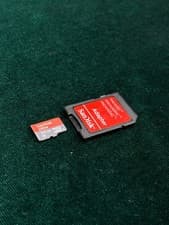
The ROS side of this project runs from a Docker image on the Pi, which is a different order of disk use from a bare Raspberry Pi OS. Size the card for the image plus the maps a SLAM run writes, and expect the card to be the part that fails first on a robot that gets its power cut by a battery protection circuit.
Assembly
- Keep a second card flashed and ready, since a corrupted filesystem on the robot costs an evening.
- Shut the Pi down before switching the pack off, rather than letting the low voltage cutoff do it.
- Write the maps to a mounted directory outside the container, or they leave with it.



17.2D LiDARBuy it
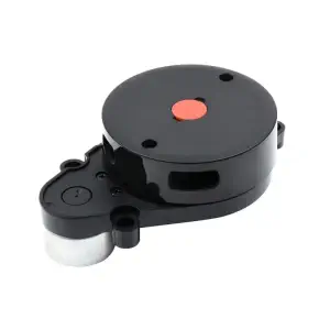
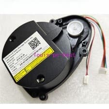
One published build ran Hector SLAM on an RPLIDAR A1M8 with a Raspberry Pi 4 and 2 GB, and ORB-SLAM2 on a camera for comparison. A walking robot is a harder platform than a wheeled one for this: the turret pitches with every step, and the scan that arrives is distorted by the gait rather than by the sensor. Mounting the unit as high and as centred as the body allows is most of the work.
Assembly
- Weigh the turret before mounting it, since the payload upstream quotes is about one pound for the whole robot.
- Mount it above every other part, or the scan maps the robot's own head.
- Slow the gait down for a mapping run, because scan distortion grows with body speed.
- Power the turret motor from the board's 3 A rail rather than from a Pi header pin.


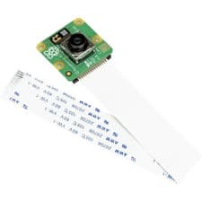
18.Camera for the PiBuy it
Visual SLAM and the imitation learning work both need a camera on the Pi rather than the I2C module of phase five, since they want frames and not a detection result. A rolling shutter sensor on a walking robot produces images sheared by the step, which visual odometry reads as motion that did not happen.
Assembly
- Prefer a global shutter sensor if the camera is used while the robot walks.
- Match the ribbon connector to your Pi revision, which changed between generations.
- Fix the focus once and lock it, since a walking robot vibrates an unlocked lens out of focus.
- Record a dataset with the robot on its stand first, so the algorithm is debugged before the gait is added to the problem.


Parts are selected by the search engine on price, stock and specifications, never on affiliate commission. Robotitem does not test these products.